How to repair a Weathermatic SLW20 Sensor Station
We use an SLW20 to control the watering schedule of the sprinklers in
our yard. In about 8 years, we have had the SLW20 fail twice, once
after 5 years, the next after 3 years. Since these are not cheap
(about $200/piece), I decided to investigate after the second failure.
Turns out that in addition to the field-replacable 9V battery, there
is a non-replacable 3V CR2032 coin cell built into the station. When
this coin cell drains, the station dies. Fortunately, it's not hard
to convert the SLW20 to make the coin cell replacable.
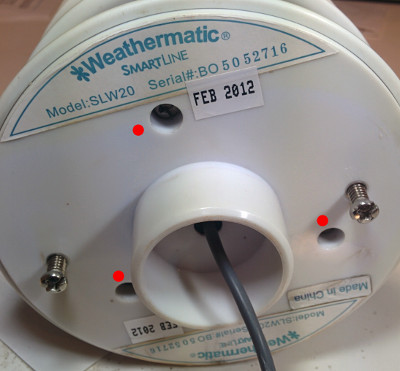
- Remove the three screws from the base of the SLW20. The screws
are marked with a red dot in the picture below.
- Remove the side cover (two Phillips screws) housing the 9V battery.
Under the cover, you should see this:
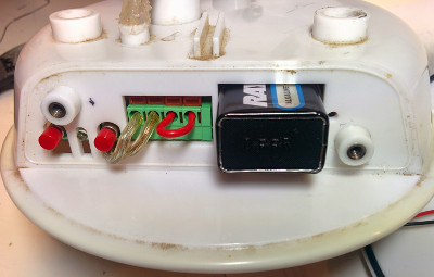
- Remove the 9V battery and the two wires with clear insulation
that go into the green termination block. Do this by using a
flathead screw driver to push in the brown sliders above the
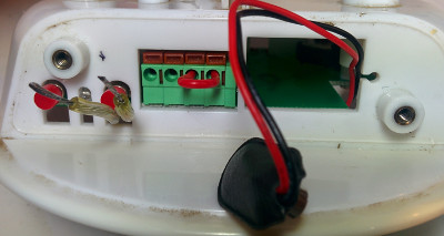
respective hole and then gently pulling the wire out. It should
look like this now:
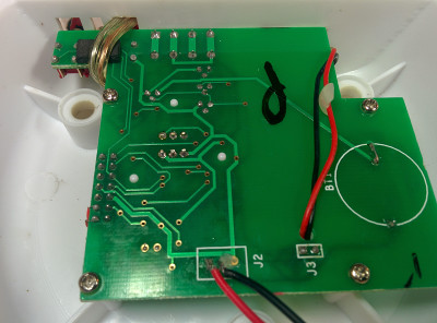
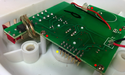
- Now pop the bottom off the SLW20. You should see a PCB that
looks similar to one in the photo below. Pay attention to the
routing of all the wires, in particular the clear wires in the top
left. You'll have to use the same arrangement to close up the
unit later on.
- Remove the four Phillips screws marked with red dots in the
photo below. Once these screws are removed, angle up the PCB
while, from the other side, pulling down the plastic rod housing
the temperature sensor (yellow dot). That should let the
temperature-sensor rod unplug from the PCB and let you gently
remove the PCB.
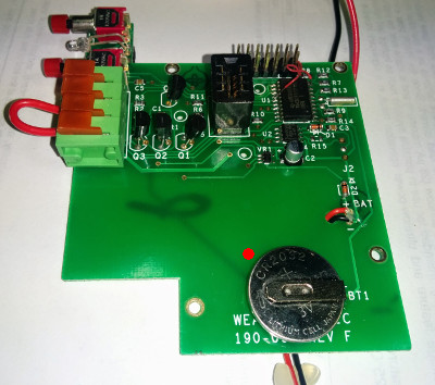
- The old CR2032 coin cell can now be found on the top side of the
PCB, marked by red dot in the photo below. Desolder this battery
and recycle it.
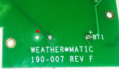
- To be able to replace the battery in the future without
soldering using a standard CR2032 cell, I installed a 20mm
coin-cell holder. I used a Keystone Electronics 1066 (Digi-Key
1066K-nD, $1.58/pc). The cell-holders pins are further apart than
the pins on the original battery so I had to drill a hole in the
PCB for the second pin, shown by the red dot in the photo below.
With that hole in place, I could then solder in the holder and
wire up the negative pin to the old trace with a short piece of
wire.
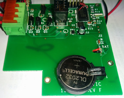
- This is what the PCB looks like in the end, with the new CR2032
cell installed.
- You can confirm that the board is working by attaching the 9V
battery and then briefly pushing the left push-button. The LED
should blink green and red.
- Now all that's left to do is to reassemble the unit in reverse
order and you're done. Happy (controlled) watering!
dmosberger@gmail.com / Last updated:
Thu Mar 26 10:54:56 2015